Conversion from Moore machine to Mealy Machine
In the Moore machine, the output is associated with every state, and in the mealy machine, the output is given along the edge with input symbol. The equivalence of the Moore machine and Mealy machine means both the machines generate the same output string for same input string.
We cannot directly convert Moore machine to its equivalent Mealy machine because the length of the Moore machine is one longer than the Mealy machine for the given input. To convert Moore machine to Mealy machine, state output symbols are distributed into input symbol paths. We are going to use the following method to convert the Moore machine to Mealy machine.
Method for conversion of Moore machine to Mealy machine
Let M = (Q, ∑, δ, λ, q0) be a Moore machine. The equivalent Mealy machine can be represented by M' = (Q, ∑, δ, λ', q0). The output function λ' can be obtained as:
Example 1:
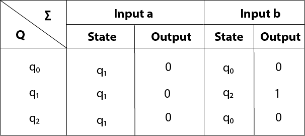
Convert the following Moore machine into its equivalent Mealy machine.
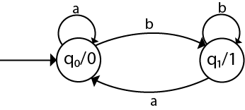
Solution:
The transition table of given Moore machine is as follows:
| Q | a | b | Output(λ) |
|---|---|---|---|
| q0 | q0 | q1 | 0 |
| q1 | q0 | q1 | 1 |
The equivalent Mealy machine can be obtained as follows:
The λ for state q1 is as follows:
Hence the transition table for the Mealy machine can be drawn as follows:
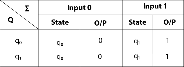
The equivalent Mealy machine will be,
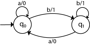
Note: The length of output sequence is 'n+1' in Moore machine and is 'n' in the Mealy machine.
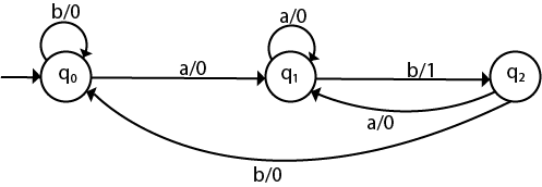
Example 2:
Convert the given Moore machine into its equivalent Mealy machine.
Solution:
The transition table of given Moore machine is as follows:
| Q | a | b | Output(λ) |
|---|---|---|---|
| q0 | q1 | q0 | 0 |
| q1 | q1 | q2 | 0 |
| q2 | q1 | q0 | 1 |
The equivalent Mealy machine can be obtained as follows:
The λ for state q1 is as follows:
The λ for state q2 is as follows:
Hence the transition table for the Mealy machine can be drawn as follows:
The equivalent Mealy machine will be,
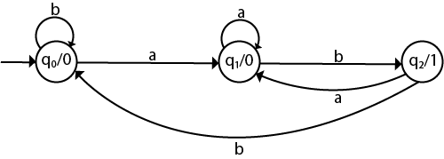
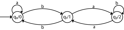
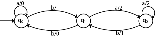
Example 3:
Convert the given Moore machine into its equivalent Mealy machine.
| Q | a | b | Output(λ) |
|---|---|---|---|
| q0 | q0 | q1 | 0 |
| q1 | q2 | q0 | 1 |
| q2 | q1 | q2 | 2 |
Solution:
The transaction diagram for the given problem can be drawn as:
The equivalent Mealy machine can be obtained as follows:
The λ for state q1 is as follows:
The λ for state q2 is as follows:
Hence the transition table for the Mealy machine can be drawn as follows:
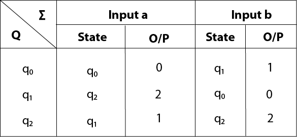
The equivalent Mealy machine will be,
Conversion from moore machine to mealy machine
Let us take the moore machine of Figure 1 and its transition table is shown in Table 3. Step 1. Construct an empty mealy machine using all states of moore machine as shown in Table 4.
| Input=0 | Input=1 | |||
| Present State | Next State | Output | Next State | Output |
| q0 | ||||
| q10 | ||||
| q11 | ||||
| q20 | ||||
| q21 | ||||
Table 4
Step 2: Next state for each state can also be directly found from moore machine transition Table as:
| Input=0 | Input=1 | |||
| Present State | Next State | Output | Next State | Output |
| q0 | q10 | q20 | ||
| q10 | q10 | q21 | ||
| q11 | q10 | q21 | ||
| q20 | q11 | q20 | ||
| q21 | q11 | q20 | ||
Table 5
Step 3: As we can see output corresponding to each input in moore machine transition table. Use this to fill the Output entries. e.g.; Output corresponding to q10, q11, q20 and q21 are 0, 1, 0 and 1 respectively.
| Input=0 | Input=1 | |||
| Present State | Next State | Output | Next State | Output |
| q0 | q10 | 0 | q20 | 0 |
| q10 | q10 | 0 | q21 | 1 |
| q11 | q10 | 0 | q21 | 1 |
| q20 | q11 | 1 | q20 | 0 |
| q21 | q11 | 1 | q20 | 0 |
Table 6
Step 4: As we can see from table 6, q10 and q11 are similar to each other (same value of next state and Output for different Input). Similarly, q20 and q21 are also similar. So, q11 and q21 can be eliminated.
| Input=0 | Input=1 | |||
| Present State | Next State | Output | Next State | Output |
| q0 | q10 | 0 | q20 | 0 |
| q10 | q10 | 0 | q21 | 1 |
| q20 | q11 | 1 | q20 | 0 |
Table 7
This is the same mealy machine shown in Table 1. So we have converted mealy to moore machine and converted back moore to mealy.
Note: Number of states in mealy machine can’t be greater than number of states in moore machine.
Example: The Finite state machine described by the following state diagram with A as starting state, where an arc label is x / y and x stands for 1-bit input and y stands for 2- bit output? 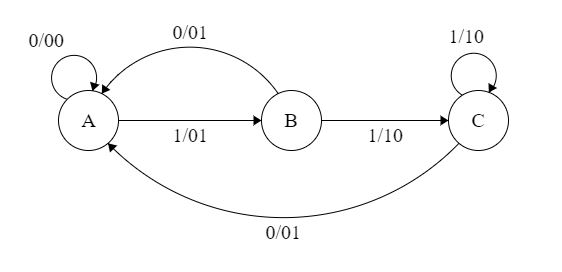 Outputs the sum of the present and the previous bits of the input.
- Outputs 01 whenever the input sequence contains 11.
- Outputs 00 whenever the input sequence contains 10.
- None of these.
Solution: Let us take different inputs and its output and check which option works:
Input: 01
Output: 00 01 (For 0, Output is 00 and state is A. Then, for 1, Output is 01 and state will be B)
Input: 11
Output: 01 10 (For 1, Output is 01 and state is B. Then, for 1, Output is 10 and state is C)